
3D Printed Parts
Each year for the past several years our robots have featured an increasing amount of 3D printed parts. Many of the parts are simple spacers that could easily be done on the lathe, but it is faster to print these parts. Some parts are more complex and are simply not possible for our team to make without the use of 3D printers.
Following the step-by-step directions model the part and place it in your folder in the Onshape training folder. Once complete let a coach know so that it can be reviewed.
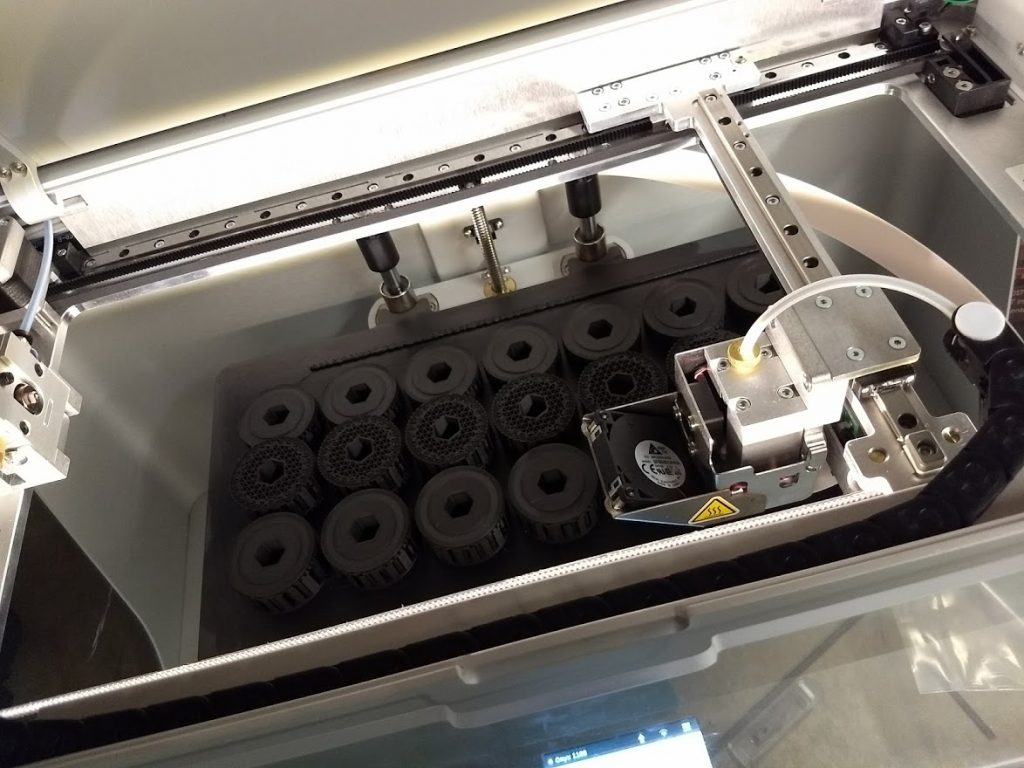
The Machine
Team 1188 owns multiple 3D printers. The printers which are used to make most of the real robot parts are the two Markforged Onyx printers. These printers use a special filament that is primarily nylon but also contains chopped carbon fiber. One of the Onyx printers can also lay down continuous fiberglass string into the print. This makes for incredibly tough parts that have strengths close to that of aluminum.
The Process
We will get into the full details of Onshape to 3D print in a later exercise but in general terms, it is a pretty easy process to go from Onshape to print. You simply need to export an STL file of your part, import that STL into Eiger.io, make a few settings, and hit print. One of the reasons we love the Markforged printers is Eiger. It’s a cloud-based slicer that is incredibly easy to use.
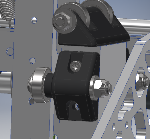
About the Part
This part was from our 2019 robot elevator. It was used to hold the hold a bearing in place and limit the lateral movement of the elevator carriage. In total there were 8 of these parts on the robot.

Step 1
We’ll start with a simple profile sketch that will serve as the base primitive for part.

- Click Sketch
- Select the Front plane to start a sketch on that plane.
Note: Every sketch must be anchored to a plane or face.
Note: In Onshape faces/planes will highlight orange to let you know that you are picking them.

- On the view cube, click the Front face. This will align your view to the front plane and make creating the sketch much easier.
Step 2

To start with we are going to draw a circle that represents the round top of the part. Don’t worry that it’s a complete circle vs. an arc. We will clean that up with trim tools latter.
- Select the Circle command
- Click the Origin Point (the small circle in the middle of the screen). Remember to look for orange highlight to know you are picking the center. To begin with, just drag the circle out and click anywhere.
- Pick the Dimension tool and then the circle.
- Drag the dimension out and enter 0.66.
 | Notice that your circle changes from blue to black as soon as you add the dimension. This is because the circle is now fully constrained. This means that it will not shift. Everything you model should be fully constrained. |
Step 3

Next you will rough in the rest of the sketch. Dimensions can be added later.
- Pick the Line tool.
- Start the line by picking a point that is a bit to the left and above of the origin point. Be very careful not to snap the line to the circle.
- Roughout the rest of the shape. Take care to ensure that vertical lines are vertical and horizontal lines are horizontal.
- Click the final point again making sure not to snap to the circle.
| As we continue the sketch you will be adding more constraints. Constraints add logical relationships or restrictions to your sketch, model, and even assembly. Most software, including Onshape, will automatically add a lot of constraints for you. Watch as you draw your lines for small black shapes to appear near your cursor. This is the software telling you it will add the constraint. |
Step 4

We will now add Tangent constraints to the two angled lines.
- Click the Tangent Constraint icon.
- Click the correct quadrant of the circle as shown in the image. Note that picking the wrong quadrant will constrain the line to the wrong tangent of the circle.
- Pick the line to establish the constraint. Notice that your sketch will shift a little bit.
- Repeat steps 1-3 on the opposite line.
Step 5

Next add the dimensions as shown above. You will be done when everything is black except for the two points on the lines that are tangent to the circle.
| Sometimes when dimensioning sketches you may find that the shape distorts in an unexpected way. Typically you can avoid this by strategically placing dimensions such that the shape stretches in a controlled way. As an example, you should place the two 0.25 dimensions before you place the 0.44 in the above image. |
Step 6

Use the Trim and Extend commands to finish cleaning up the sketch. You will need to trim/extend the two angled tangent lines. Once you’ve finished the angle lines trim the circle into a tangent arc.
| At this stage, the entire sketch should be black. There should be no blue lines or points left. If there are you’ve made a mistake somewhere. |
Step 7
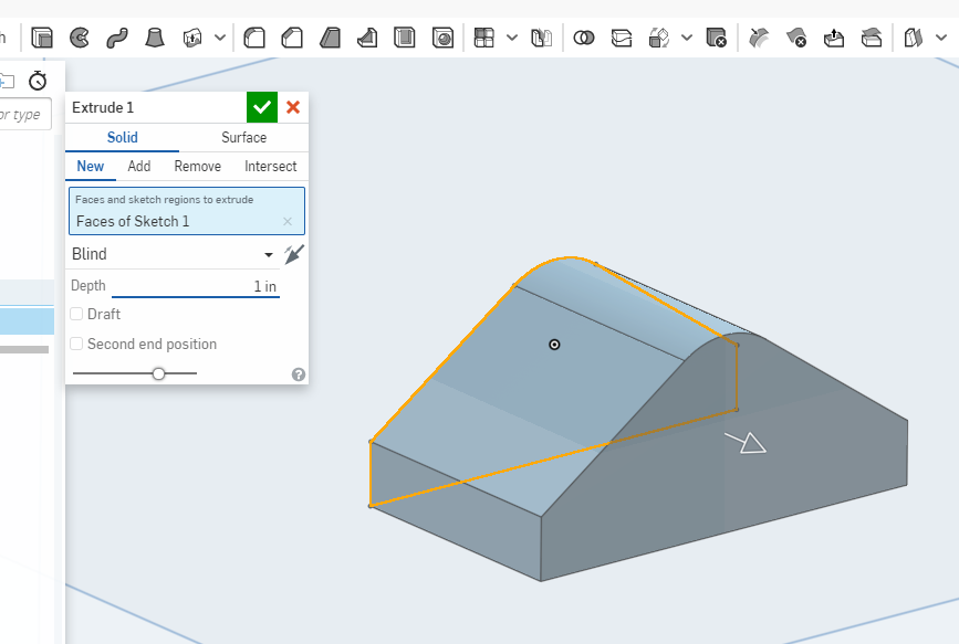
Extrude the sketch 1”
| An easy way to look at your model is to orbit. You can quickly orbit in Onshape by holding shift+middle mouse button while moving the mouse. |
Step 8

Create a new sketch on the front face and add a circle making sure to click on the origin point. Add a dimension of 0.27 to the circle.
| The whole added in this part is for a 0.25” bolt yet it is sized to 0.27”. The reason for this is a 0.25 bolt will not fit through a 0.25 hole due to manufacturing tolerances. Keep this in mind whenever designing parts. Learning how much tolerance to build into your parts will take time. If you are unsure, ask a more experienced designer. |
Step 9

Next well cut the hole through the part.
- Pick the extrude command.
- Select the circle.
- Set the extrusion operation to Remove.
- Set the depth to Through All.
Step 10
Now that we have the primitive shape of our part we will add the two recessed bolt slots. To make the slots we are going to be using some new tools for construction geometry.

In order to create the slots we need to create a sketch in middle of the part. Since there is no surface there to put our sketch on we need to make a Construction Plane.
- Orbit the part so that you can see the bottom face as shown.
- Pick the Plane button.
- Select the bottom face of the part.
- Click the direction arrow to flip the offset direction.
- Set the offset distance to 0.25”
Step 11

Create a sketch on the plane we just created and align your view to top.
| Projected geometry allows us to attach sketch geometry to parts of the existing model. In this case, we are projecting the outside edges of the part so that we can draw our slots constrained to them. This is important because if this part became larger in the future we want to make sure that the slots are constrained to the outside edges. |
- Pick the Use button.
- Pick the two outside edges of the part.
Step 12
We will now draw a centerline and the two outside edges of our slots.

- Pick the line tool
- Pick the midpoint of each of the lines that you projected in the last step.
You will know you are snapping to the midpoint when you see the midpoint constraint icons on your screen. Make sure you see these before clicking. - Pick the Offset command.
- Offset a line 0.17 above the centerline.
- Offset a line 0.17 below the centerline. You will need to select the on-screen arrow to flip the direction of the offset.
- With nothing else selected, select your centerline.
- Pick the Construction command to make your centerline a construction line. This tells the software to ignore this geometry when using extrude or revolve commands.

Step 13

We’ll now finish up this sketch by adding some circles and trimming our lines back.
- Add a circle to each side.
When you pick the center point of the circle, make sure that thecoincident constraint is the only one that is being applied.
When you pick the radius point, make sure that the tangent constraint to the horizontal line is shown.
- Using the dimension command snap to the center of the circle then to the origin point. Set the dimension to 0.5.
- Repeat on the other side.
- Use the trim command to clean up the lines between the circles.
Step 14

Orbit the part (shift+middle mouse) and execute the extrude command.
- Set the operation type to Remove.
- Click the direction arrow to reverse it.
- Set the distance to Through all.
| The default value for extruding is set to 1”. In this case 1” seems to work fine to remove the material however when designing you must always consider the future changes to the part. Setting the depth to Through all ensures that no matter what change is made to the height of the part the pockets will still be cut correctly. |
Step 15

- Start a new sketch based on the pocket face.
- Project the pocket arc using the Use command. Place a circle on the center point of the projected arc.
- Set the diameter of the circle to 0.21
- Extrude the hole through all.