
CNC Parts – Tubes

The most common parts we make are machined aluminum tubes. We use mostly 1”x1” and 2”x2” aluminum tubes on 1188. The wall thickness of the tubes can vary, and it is important to get the thickness correct. Most of our tubes are either 1/8” or 1/16” wall thickness.
Following the step-by-step directions model the part and place it in your folder in the Onshape training folder. Once complete let a coach know so that it can be reviewed.
The Machine
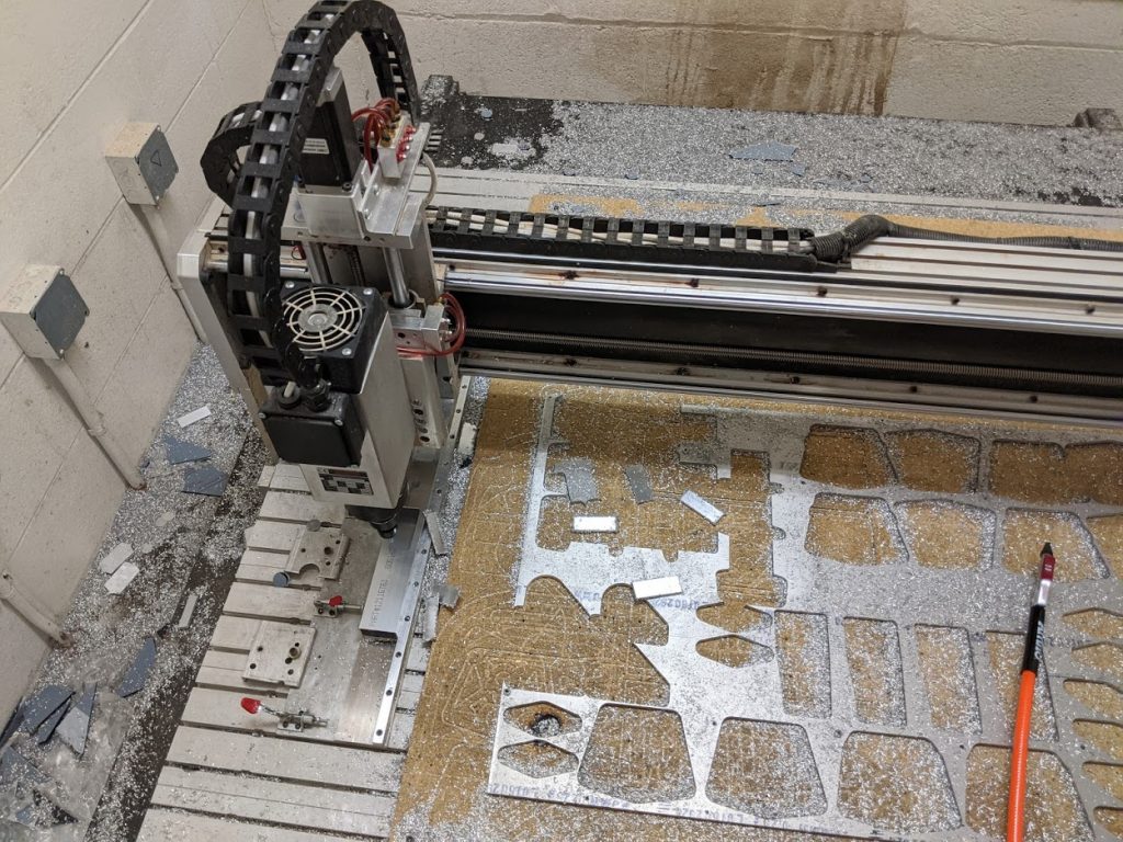
Team 1188 has a Velox 5050 CNC router. The difference between a typical CNC and a CNC router is that a CNC router is known as a 2.5D CNC vs. a true 3D CNC. The Velox has full X/Y travel but unlike a normal CNC, the Z-axis on the Velox can only travel directly up and down. This somewhat limits what parts can be made but it works well for robotics.
On the Velox, we can cut aluminum & plastic up to 4′ x 4′. Most commonly we cut aluminum plates and tubes as well as polycarbonate plastic sheets.
About the Part & Process
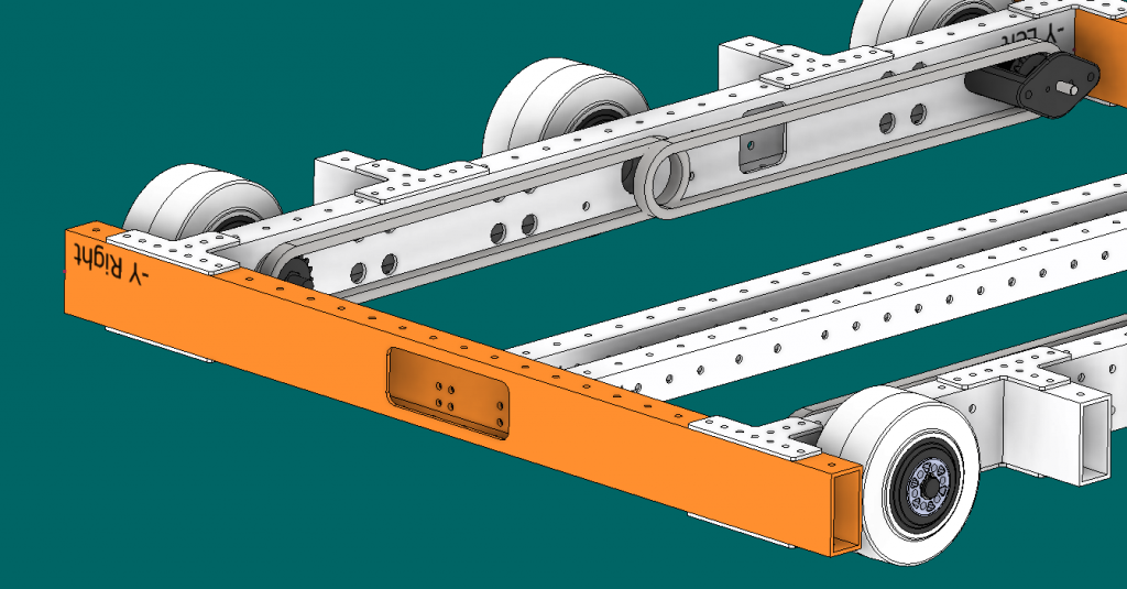
This tube was part of the lower frame on the 2019 robot. The robot had two of these, one for the front frame rail and one for the rear frame rail. Back in 2019, the robot was designed in Inventor, a competing CAD program to Onshape. Once the part was designed in CAD it was taken into a CAM program. CAM programs allow us to build up the computer code that will tell the CNC what to cut. Since this is our first exercise we’re going to skip the CAM part and stick with just the CAD modeling.
Step-by-step
Using the drawing on the following page model the tube and place it in your folder in the Onshape training folder. Once complete let a coach know so that it can be reviewed.

Step 1
We’ll start with a simple profile sketch that will serve as the base primitive for part.

Start a new sketch on the Front plane and align your view to front.
Click the dropdown arrow next to the rectangle (A) and select Center point rectangle (B)
 | This exercise assumes that you are familiar with basics concepts and the use of Onshape. It will skip a lot of specific steps, like how to make new sketches. Make sure you have completed the basic introduction training provided by Onshape before jumping into this exercise. |
Step 2
We’ll now draw the rectangle making sure to constrain it to the origin point.

- Pick on the origin point to set the center point of your rectangle.
- After finishing the rectangles rough shape, add dimensions. 1” at the top and 2” on the side.
- Extrude the rectangle 25”.
| For purposes of standardized CNC work all tubes should have their main section (1”x2” in this case) drawn on the front view. |
Step 3
Now hollow out the tube using the Shell command.

- Select the Shell command.
- Select BOTH ends of the tube. Remember you can use the Shift+Middle button to orbit the part. Make sure you see two faces in the Faces to remove the box.
- Set the Shell thickness to 1/16”.
Step 4

We are now going to make the holes that run along the top and bottom faces of the tube. This will be the first time we’re using the pattern command. This command can be tricky in OnShape. If you get stuck ask for help.
Begin by starting a new sketch on the top face of the tube, align your view, and zoom in near the origin point.
- Select the circle command.
- Place the center of the circle by hovering over the origin point then move your mouse down about ½” from the origin point. Make sure you see the
vertical constraint.
- Dimension the circle to 0.156 or 5/32.
- Dimension the center of the circle to the origin point 0.5”
Step 5

Next we are going to pattern the circle but before we setup our pattern let’s review the settings of the pattern command.
- This number sets how many instances of the pattern you want in each direction. In this case, we’ll get three copies to the right and on up. Note that the selected object counts so you will never have less than 1.
- This dimension sets the distances between copies. Notice that there is no dimension in the up direction. That is because up is set to only one instance. Setting it to any number greater than 1 and a dimension will show up.
- By default, the pattern goes to the right and up. Clicking the small arrow will flip the direction.
Step 6

- Pick the Linear Pattern command.
- Select the circle.
- Flip the vertical direction by clicking on the arrow.
- Set the vertical quantity to 25 (1 per inch of the tube)
- Set the horizontal quantity to 1
Pick any point not on an object to end the command and lock in the pattern.
Step 7

- Click on the Extrude command. All the holes should select automatically.
- Change the type to Remove.
- Set to Through all.
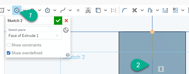
Step 8

Next, we are going to cut the 8 holes on the right side of the tube. To start with we need a construction line in the middle of the tube.
- Pick the Line command.
- Making sure to snap to the middle point
both times you pick endpoints for the line.
- Change the line to a construction line.
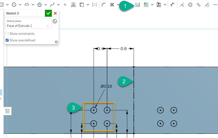
Step 9

- To the left of the centerline draw 4 circles roughly in a square pattern.
- Dimension one of the circles to 0.18 diameter.
- Use the equal constraint to make all the circles the same size. To do this, pick the equal button then pick the circle you dimension, next pick any of the other circles. This will force their diameters to be the same. Repeat this for the other circles until all 4 are the same diameter.
Step 10

Dimension all 4 holes per the drawing.
| This sketch would be cleaner by using the vertical and horizontal constraints. This would have eliminated half of the dimensions. |
Step 11
We now need to mirror the 4 holes about the centerline.
- Select the Mirror command.
- Pick the centerline
- Window select the 4 holes.
Step 12

- Set the operator to Remove
- Reverse the direction of the extrude by clicking the arrow.
- Set the distance to Up to next.
Step 13

The last thing to add to this part is the rectangular opening on the left side of the tube. To do this you will need to;
- Create a new sketch on the Left face of the tube.
- Draw a rectangle.
- Dimension the rectangle. You’ll know you have all the dimensions when all the blue lines turn black.
- Use the fillet command to round all 4 corners with a radius of 0.25.
- Use the extrude command to cut the opening. Use the same settings that you used to cut the 8 holes.
That’s it. Your part is finished. Make sure it is in your training folder and notify the coach that it is ready for review.
NEXT – Exercise 2 – Bearing bracket